How the height of a 3D bridge is calculated
With view_3d=True, roadstyle draws each bridge as a raised deck. The deck rises from the ground along a ramp, stays at one height, and comes down again.
Two programs make this picture, one after the other. This page explains what each program does and gives the formulas. To switch the bridges on or off, read Bridges in 3D.
Two parts: the engine makes the profile, the page draws it
- The engine (Rust,
decks.rs) runs when you make the page. It finds the bridges, joins them into groups, and calculates the profile of each group. The profile is a list of deck pieces in the style sourcedecks. The engine does not draw. - The page (
bridgemesh.js) runs in the browser. It reads the profile, adds the height of the ground, and draws the pieces as one mesh. The page does not find groups and does not calculate group heights.
The format of the profile
The profile is a GeoJSON FeatureCollection in the source decks of the style. It is plain data in the page. Each deck piece is one Feature: a polygon (the outline of the piece on the map) and its properties.
After each deck piece, the source holds the two casing slabs of that piece. A casing slab has __rs_casing_slab: 1 and the same group, chain, lift and place values.
This is the first piece of a straight bridge of 120 m with the default look. The numbers are rounded to 4 digits. … marks the properties that are the road's own columns and the colors and widths of its look.
{
  "type": "Feature",
  "properties": {
    "highway": "primary", "bridge": "yes", "layer": "1", "edge_id": 1,
    "…": "the road's columns and the look values",
    "__rs_group": 1,
    "__rs_chain": 1,
    "__rs_full": 6.8889,
    "__rs_thick": 1.0,
    "__rs_lift0": 0.0,
    "__rs_lift1": 0.006,
    "__rs_s0": 0.0,
    "__rs_s1": 0.02083,
    "__rs_base": 0.01,
    "__rs_height": 1.01,
    "__rs_enda": [7.42, 43.74],
    "__rs_edges": [0]
  },
  "geometry": {
    "type": "Polygon",
    "coordinates": [[[7.42, 43.740022], [7.420031, 43.740022], [7.420031, 43.739978], [7.42, 43.739978], [7.42, 43.740022]]]
  }
}
| Property | Meaning |
|---|---|
__rs_group |
The number of the group |
__rs_chain |
The number of the chain (a line of bridge roads, see step 2) |
__rs_full |
The group height H, in metres |
__rs_thick |
The thickness of the deck, in metres |
__rs_lift0, __rs_lift1 |
The lift at the start and at the end of the piece, from 0 (ground) to 1 (H) |
__rs_s0, __rs_s1 |
Where the piece starts and ends along its chain, from 0 to 1 |
__rs_base, __rs_height |
The underside and the top of the piece at its middle, without terrain. The page uses them for clicks |
__rs_enda, __rs_endb |
The two end nodes of the chain, as longitude and latitude. Only the first piece has __rs_enda, and only the last piece has __rs_endb |
__rs_edges |
The roads of the piece |
The names with __rs_ are internal names of the engine. They can change.
The bridge of 120 m has 47 deck pieces. These are the values that matter, for the first five pieces, the middle piece and the last two pieces.
| Piece | __rs_s0 |
__rs_s1 |
__rs_lift0 |
__rs_lift1 |
|---|---|---|---|---|
| 1 | 0 | 0.02083 | 0 | 0.006 |
| 2 | 0.02083 | 0.04167 | 0.006 | 0.0232 |
| 3 | 0.04167 | 0.0625 | 0.0232 | 0.0505 |
| 4 | 0.0625 | 0.08333 | 0.0505 | 0.0868 |
| 5 | 0.08333 | 0.10417 | 0.0868 | 0.131 |
| … | ||||
| 24 | 0.45926 | 0.54074 | 0.9972 | 0.9972 |
| … | ||||
| 46 | 0.95833 | 0.97917 | 0.0232 | 0.006 |
| 47 | 0.97917 | 1 | 0.006 | 0 |
The pieces join with no gap. The end lift of one piece is the start lift of the next piece, and __rs_s1 of one piece is __rs_s0 of the next. The pieces of a ramp are short (2.5 m).
The piece on the flat part is long.
Part 1. The engine calculates the profile
The engine works in five steps. Each step uses the result of the step before it. These symbols are in the formulas.
| Symbol | Meaning |
|---|---|
| L | The length of a group, in metres |
| H | The group height, in metres |
| g | The grade: metres of ramp for 1 m of height |
| R | The full ramp: metres of ramp for the full height |
| ℓ | The length of a chain, in metres |
| x | The distance along a chain from its start, in metres |
| lift | The part of H that the deck has, from 0 to 1 |
1. Find the 3D bridges
A road is a 3D bridge when two conditions are true. Its bridge value is yes, and its level (lvl) is 1 or more. A bridge at level 0 or less stays a flat line.
A two-way road is one bridge road. The engine draws it as two half-width ribbons, one for each direction.
2. Join the bridges into groups
Bridge roads that share a node are one group. The level of the roads does not matter. A group has one height, so two roads of one group have the same height at the node where they meet.
Inside a group, the engine joins roads into chains. A chain is a line of bridge roads through nodes where only two bridge roads meet. The engine makes one deck for a chain, with no seam. A node where three or more bridge roads meet is the end of a chain.
A free end is a node where only one bridge road ends. The deck meets the ground at a free end.
The length of a road is the sum of its segments in metres. The length of a group, L, is the sum of the lengths of its roads. A two-way pair counts one time.
3. Give each group a height
The group height, H, is the height of the deck above the ground on its flat part. The engine finds H in one of two ways.
From the length of the group. This is the default. A long bridge crosses something wide, so it stands higher.
With the default look, base_m is 5, max_m is 22, grow_from_m is 60 and grow_to_m is 600. So H = 5 + 17 × (L − 60) ÷ 540 between 60 m and 600 m. If grow_to_m is not larger than grow_from_m, H is base_m.
| Length of the group | H |
|---|---|
| 60 m or less | 5 m |
| 120 m | 6.9 m |
| 330 m | 13.5 m |
| 600 m or more | 22 m |
From your own value. Give bridge_heights or bridge_height_col. The engine uses your value for the whole group in place of the length rule.
Two different values in one group are an error. For the keywords, read Every parameter.
4. Find the height at each node
The height at a node is a lift from 0 to 1. Lift 0 is the ground. Lift 1 is H.
g = ramp_m ÷ base_m                 (the default: 40 ÷ 5 = 8)
R = max( H × g, 1 )                 (in metres)
node lift = min( 1, d_free ÷ R )
d_free is the distance along the roads from the node to the nearest free end of its group. It is 0 at a free end. The engine finds it with a shortest-path search from all the free ends.
A group of 5 m has a full ramp of 40 m. A group of 13.5 m has 108 m. A group of 22 m has 176 m.
The lift belongs to the node and not to the road. For this reason, two chains that meet at a node have the same height there. A node with no free end in its group, for example in a closed loop, has lift 1.
If the distance from a free end to the middle of a bridge is shorter than the full ramp, the deck does not reach H. A bridge of 40 m has H = 5 m and a full ramp of 40 m. Its deck rises only 1.8 m at the middle. A short bridge has a low, round hump and no wall.
5. Calculate the curve between the nodes, and cut it into pieces
Inside a chain, the engine finds the lift at each distance x along the chain. Let lift_head and lift_tail be the node lifts at the two ends of the chain.
a = lift_head + x ÷ R                  from the head end
b = lift_tail + (ℓ − x) ÷ R            from the tail end

cross = (ℓ + R × (lift_tail − lift_head)) ÷ 2     where a and b are equal (metres from the head end)
k = clamp( 2 × min(cross, ℓ − cross) ÷ R, 0, 0.4 )     the width of the rounding
h = max( k − |a − b|, 0 ) ÷ k                    (h = 0 when k = 0)
t = min(a, b) − h × h × k ÷ 4                    smooth minimum
t = clamp(t, 0, 1)

lift(x) = t × t × (3 − 2t)
The steps in words:
- Each end gives a lift that rises with the distance from that end (
aandb). - The smaller of the two values is the lift. The deck rises from each end and stops at 1.
- Where
aandbcross inside the chain, the deck has a crest. The smooth minimum rounds the crest over a widthk.kis at most 0.4 and never wider than the distance from the crossing to the nearer end allows. It lowers the value by up tok ÷ 4, which is 0.1. A short bridge gets a round top and no ridge. - Where
aandbcross at an end of the chain, or outside the chain, there is no crest.kis 0 and the lift is the exact minimum. For this reason the lift at a node is always exact, and a ramp that starts at a node has no dip. - The last line, t × t × (3 − 2t), gives each ramp a soft start on the ground and a soft end at the flat part. The curve is steepest in the middle of a ramp: 1.5 times the average slope, which is 1.5 ÷ 8 = 18.75 % with the default look.
The underside and the top of the deck, without terrain:
The thickness thickness_m is 1 m by default. The factor min(1, 2 × lift) makes the deck thin out to nothing at the ground, so the end of a ramp lands flush with the road.
A worked example. A straight bridge of 120 m has two free ends. L = ℓ = 120 m, so H = 5 + 17 × 60 ÷ 540 = 6.889 m and R = 6.889 × 8 = 55.11 m.
At x = 10 m: a = 10 ÷ 55.11 = 0.1815 and b = 110 ÷ 55.11 = 1.996. The two values are far apart, so h = 0 and t = 0.1815.
Then lift = 0.1815 × 0.1815 × (3 − 0.363) = 0.0868, and the underside is 6.889 × 0.0868 = 0.60 m. This is the value __rs_lift0 of piece 5 in the table above.
The engine then cuts the chain into pieces. The cut points are the two ends of the chain, the end of each ramp, and every step_m (2.5 m) along each ramp. A piece also ends where one road changes to the next.
For each piece, the engine writes __rs_lift0 = lift(x_start), __rs_lift1 = lift(x_end), __rs_s0 = x_start ÷ ℓ and __rs_s1 = x_end ÷ ℓ.
It writes __rs_base = H × lift(x_middle) and __rs_height = __rs_base + thickness_m. These pieces are the profile.
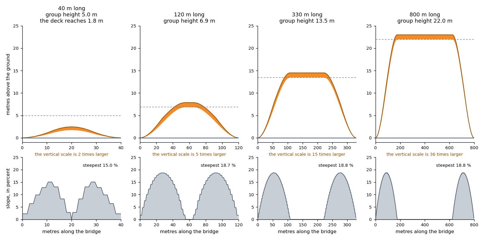
The figure shows the profile of one straight bridge for four lengths. The engine made it with the default look. In the top row, the orange band is the deck and the dashed line is H.
The vertical scale is larger than the horizontal scale, by the number under each picture (36 times for the bridge of 800 m), so a ramp looks steeper than it is. The bottom row shows the true slope in
percent. On every ramp the steepest slope is 18.8 %, which is 1.5 times the average of 12.5 %. Make the figure again with python docs/img/bridge-height/make.py.
Part 2. The page draws the profile
The page reads the pieces from the source decks. It does not calculate the lift of a piece again. For each piece, the page makes triangles: a top, two side walls and a bottom.
It draws all pieces in one custom layer, as one smooth mesh. Inside a piece, the lift at a vertex is a straight line from __rs_lift0 to __rs_lift1, by the distance along the piece.
6. Put the deck on the terrain
Without terrain, the ground height is 0, and the formulas of step 5 give the height of each vertex. When the 3D terrain is on, the page uses these values for each vertex of each side of the deck.
G      the ground height under the vertex
C      the gap = 0.3 + 2.5 × slope          (metres)
Z      the level line = za + (zb − za) × s
       (za, zb: the ground at the two ends of the chain; s: the place along it, 0 to 1)

underside = (1 − lift) × (G + C) + lift × (Z + H)
top       = underside + thickness_m × min( 1, 2 × lift )
- Close to the ground (lift near 0), the deck follows the ground under each side of its width, because a hill can slope sideways.
- From the flat part up (lift near 1), the deck is level across its width, between the ground at the two ends of the chain.
- The slope in
Cis the slope of the terrain, read 4 m to each side of the vertex. The gap keeps the start of a ramp above the terrain that the map draws. It fades out as the lift rises. - Without terrain, G, C and Z are 0, and the underside is H × lift.
If a terrain tile has not arrived, the page does not draw the chains that need it. It draws them when the tile arrives.
The other work of the page
The casing is a thin slab along each long side of the deck. The extrusion layers of the decks stay in the map with opacity 0. A click or a hover finds the bridge on them. The Street View marker stands on the deck.
A real example: the Granville Bridge
The Granville Bridge in Vancouver has a main span and many ramps. This is a real group with more than one chain. The data is 41 road edges (27 OpenStreetMap ways) from the
Vancouver database of duckOSM, in docs/samples/bridge-profile/granville_bridge_edges.parquet. The engine makes one group of them, with 12 chains, 624 deck pieces and
H = 22 m. The group is 3061 m long, so H is the largest value, max_m. A full ramp is 22 m × 8 = 176 m.
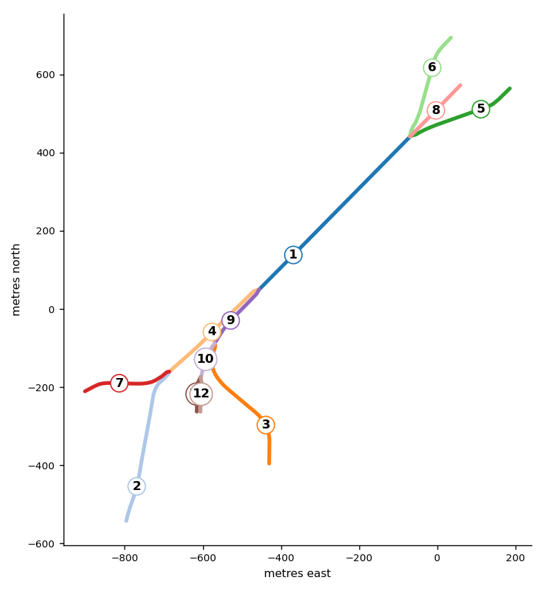
The figure shows the chains on the map. The numbers are the chain numbers of the table, from the longest chain to the shortest one. Each chain has a first end and a last end, in the order of its points.
| Chain | Roads | Length | Lift at the first end | Lift at the last end | Deck pieces |
|---|---|---|---|---|---|
| 1 | Granville Bridge | 550 m | 1.00 | 1.00 | 2 |
| 2 | Granville Bridge | 404 m | 1.00 | 0.00 | 72 |
| 3 | Granville Bridge | 367 m | 0.00 | 1.00 | 74 |
| 4 | Granville Bridge | 312 m | 1.00 | 1.00 | 4 |
| 5 | Granville Bridge, Seymour Street | 286 m | 1.00 | 0.00 | 73 |
| 6 | Granville Bridge, Howe Street | 276 m | 0.00 | 1.00 | 74 |
| 7 | Granville Bridge | 228 m | 1.00 | 0.00 | 73 |
| 8 | Granville Bridge | 184 m | 1.00 | 0.00 | 72 |
| 9 | Granville Bridge | 179 m | 1.00 | 1.00 | 2 |
| 10 | Granville Bridge | 96 m | 0.51 | 1.00 | 36 |
| 11 | Granville Bridge | 89 m | 0.51 | 0.00 | 71 |
| 12 | Granville Bridge | 89 m | 0.00 | 0.51 | 71 |
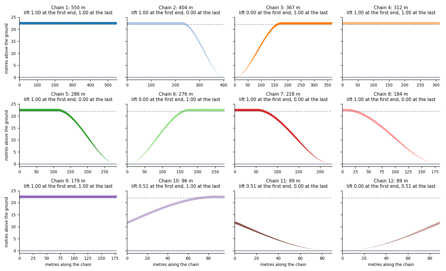
The figure shows the profile of each chain. The dashed line is H. What the example shows:
- Eight chain ends are free ends. Their lift is 0.00. The ramp rises from the ground there, along the full ramp of 176 m (chains 2, 3, 5, 6, 7, 8, 11 and 12).
- A node far from a free end has lift 1.00. A chain with lift 1.00 at both ends is flat. Chains 1, 4 and 9 each have only 2 deck pieces, one for each road.
- A node that is near a free end has a lift between 0 and 1. Chains 10, 11 and 12 meet at one node. It is 89 m from the nearest free end, so its lift is 89 ÷ 176 = 0.51. All three chains have 0.51 at that node, so there is no step.
- A short chain does not reach H. Chains 11 and 12 are 89 m long. Their decks reach only 0.51 × 22 = 11.2 m.
- All chains of the group have the same H. Chain 1, the main span, and chain 7, a low ramp, both reach 22 m. The City of Vancouver LiDAR 2022 measures other heights on the same
bridge: 39 m on the main span, and 11.6 m to 27 m on the ramps. The engine does not read measured heights. For the comparison, read
docs/design/bridge_profile_edit.md.
Make the figures and the table again with python docs/img/bridge-height/granville.py.
What can change a profile
Four things change a profile today.
| What | When | What changes |
|---|---|---|
bridge_heights, bridge_height_col |
When you make the page | H of a group. The engine makes the ramps again for the new H |
bridge_decks setting |
When you make the page | Any number in the formulas: for example ramp_m, base_m, thickness_m |
rsSetBridgeHeight(road, metres) |
In the open page | H of a group. The page keeps the lifts, so the ramps keep the length that they had with the first height |
rsSetBridges3D(false) |
In the open page | The bridges are flat lines |
The engine does not read a height or maxheight tag to find H. The height is a rule for the picture and not a measurement. Two bridges of the same length get the same H.
A planned input profile (the nodes of a group of bridges, with a height for each, which a person edits) is on The bridge profile: input and output, with sample files.
A proposal for heights from the design rules (clearance, grade, vertical curves) is in docs/design/bridge_height_design.md. Neither is built.
A step that edits the pieces between the engine and the page must keep these rules, or the mesh shows a step or a gap:
- The pieces of a chain cover 0 to 1 with no gap.
__rs_s1of a piece is__rs_s0of the next piece, and the end lift of a piece is the start lift of the next piece. - Two chains that meet at a node have the same lift at that node.
- The lift is 0 at a free end.
- All pieces of a group have the same
__rs_full. __rs_baseand__rs_heightof a piece follow its lifts. The page uses them for clicks.- The casing slabs of a piece have the same lifts and places as the piece.
A test (test_the_numbers_of_the_bridge_height_page_are_the_engines) keeps the formulas on this page equal to the engine. It calculates the lift of every piece of four bridges with these formulas and compares it with the engine.
Settings that change the height
Set these in the bridge_decks setting, for example settings={"config": {"bridge_decks": {"ramp_m": 80}}}. A longer ramp_m makes every ramp longer.
For an 800 m bridge, ramp_m: 80 moves the start of the flat part from 176 m to 352 m.
| Key | Default | What it changes |
|---|---|---|
base_m |
5 | H of a short group, and the base of the grade |
max_m |
22 | H of a long group |
grow_from_m |
60 | The length up to which H is base_m |
grow_to_m |
600 | The length from which H is max_m |
ramp_m |
40 | Metres of ramp for base_m of height. The grade is ramp_m ÷ base_m |
step_m |
2.5 | The longest piece on a ramp |
thickness_m |
1 | The thickness of the deck |
Other bridge_decks keys change the picture and not the height: width_scale, match_zoom, flat_below, casing_px and opacity.
Read Every parameter for all of them.